Doug's Telegraph Model 12 Refurbishment Project
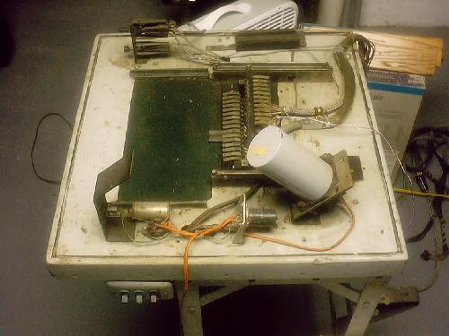
My Teletype Model 12 was owned previously by a ham who had extensively rewired the table upon which the machine sits.  He apparently had it working with a vacuum tube keyer to reduce the extensive RFI that this machine generates with its six printing magnets that each draw about 300 ma at 150 volts -- aka lots of sparks!  And as one of my first electronics teachers noted about anything that generates sparks, "Remember the first radio..."  However, I don't have the vacuum tube keyer.  In short, this table is in serious need of attention for the machine to operate. In the shot above one can easily see the huge shielded cables that went to the outboard keyer, along with some sort of switching with a relay in the front part of the photo.  Who knows what all this did.  It's got to go, especially after I discovered that all the motor wiring on this thing was done with 20-gauge wire!!  Out, out!
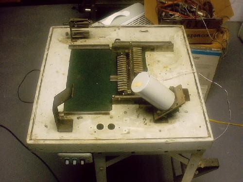
After about an hour's worth of work, I have removed just about all of the old wiring from the table.  However in doing this and working "up close and personal" with the table, I can see that it really should be repainted.  Any reference materials that I have seen for the Model 12 shows it with a black table and cover.  My example is all in gray, though I can see original gloss black (black japan?) in the area under the contact blocks in the center of the table, telling me that perhaps this was the original color of my machine, too.
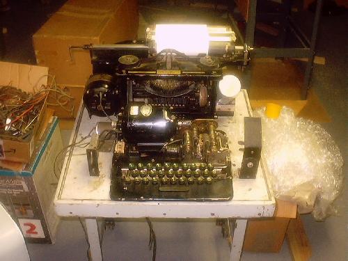
Above is a shot of the Model 12 as it exists at the moment.  I need now to think about what I am going to do about repainting the steel plate base of the machine.  Also I am thinking about perhaps building a transistorized keyer for the machine to keep the RFI down.  Check back periodically to see if the project has gotten any further.  I would like to keep a picture gallery and journal going here of the progress.


January 5, 2003 -- I have wired up a 150 VDC power supply to run the print magnets.  The table is now wired "straight," i.e. no electronic keying.  However, the machine isn't running quite right yet.  It probably (probably? definitely!) needs a good oiling & lube, as well as some reworking of the wiring in the keyboard.  I discovered that the keyboard/distributor unit has been rewired sometime in its past.  While it is neatly done, the connections involving the latch magnet on the receiving distributor don't match the published schematics I have from some old ham radio publications.

Also, the main print clutch has a few issues.  After rotating once to print a selected character, the clutch does not fully disengage from the driving gear.  I am not sure at this juncture whether it is a lubrication or bearing issue.
Late January 2003 -- Lubrication was the issue with the main print clutch.  Adding oil to the various oil cups and into the center of the printer drive shaft has the printer running a bit more smoothly and the print clutch now operates correctly!  However, the printer still does not accurately print characters typed at the keyboard.  Part of the problem is suspected to be the keyboard unit's wiring which on quick inspection does not appear to be correctly wired for the incoming signal distributor.  Also, the polar relay is suspected of being out of adjustment.  A call for help among some friends yielded a section from a US Army technical manual on the proper adjustment of a polar relay.  Now to find some time to do it...

The typing unit's motor also appears to have a start contact problem.  A faint "ticking" noise is heard inside the motor when it is operating, and a definite smell of ozone permeates the air indicating arcing going on someplace.  Need to figure out how to open the motor to assess the start contacts.


Return to my telegraph page

Return to home


Updated July 14, 2014