Doug's SxS Switch -- The Early Days   
Current Progress   Feb 2004 - April 2004    May 2004 - Aug 2004   Sept 2004 - Dec 2004   Jan 2005 - Jan 2008


December 2003 - January 2004


28 December 2003 -- After more than ten years I have finally gathered up enough step gear to start building a small Step-by-Step or Strowger switch.  I came up with a 19" equipment rack and have started to mount rails on which to hang the switches.  Standard telephone equipment racks are usually 23" wide, but this one was available to me.  Since I am custom building the equipment rails to the rack anyway, it really didn't matter what size rack I had.

Below are two photos of the rack after the first day's work.  One complete rail is up and I could hang a line finder (top) and a connector (bottom).  You can see the next rail clamped into place, getting ready to drill mounting holes for the nuts & bolts.  Ultimately the switch will be a two-path, three-digit switch to serve about 40-60 telephones.


29 December 2003 -- The next two photos are after the second day.  All the rails are in place for the switches I plan to use and all the switches are on the equipment rack.  The top row, from left to right, are two 33014 line finders (all equipment is Western Electric, of course!), and a 32077 selector.  Bottom row l-r are two 31739 connectors, and a 30200 selector.  That particular selector, by the way, was manufactured in 1942!


Things are on hold (pun intended) for the moment as I am awaiting delivery of contact banks for the selectors and connectors, which will no doubt have to be rewired.  I am seeking contact banks for the line finders -- if you have any, let me know! (email link below)  I am also looking into building up the line and cutoff relay circuits and am exploring doing that by having printed circuit boards made. It will be a tradeoff of time vs. money, I can see that already.

I am going to try to keep this page up-to-date, so check back from time to time.


Spent some quality time with the switch frame a couple of days after the photos above were taken and got working with the line finder units.  I purchased them almost 15 years ago and never had put power to them and with some freshly acquired technical data about them, I set out to get them working.  They work, but not after a bit of work and adjustment.  The one finder's 11th rotary position switch was out of alignment was always contacting, so it prevented the finder from working at all.  A little work with a long-nose pliers on that switch leaf and that finder was good to go.

The other finder was another story, however!  It had various issues, ranging from the 'A' relay's armature being completely out of alignment, to mechanical problems with the vertical stepping mechanism and components.  With having the working finder, it was nice to be able to put the units side-by-side to see how things SHOULD be and make them so.  After a number of careful adjustments and tests, this once-errant finder was again working properly.  Or, at least as properly as it can without contact banks on which to actually find a connection!

13 January 2004 -- got word today that the contact banks for the selectors and connectors are on the way!
15 January -- the contact banks arrived!  It's a strip of six banks, which have to be separated and rewired for my little switch.  I already have two banks in the process of disassembly.  Looks like these banks have been sitting around for a while and are pretty grimy.  Taking them apart completely will allow for a thorough cleaning and burnishing of all the contacts so everything works well.  It'll take a while, but it should be well worth the effort.
19 January -- Lots of progress to report!  The morning's email brought word that there are line finder contact banks on their way! In another email a deal was worked for the equipment jacks for the switches.  Progress indeed.

Here's some photos of things going on in the last few days with the switch project.  The selector and connector banks need a fair bit of TLC to get them ready for use. Below are pictures of a sleeve bank before and after contact cleaning. The one on the left shows the crud on the contacts.

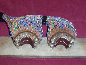
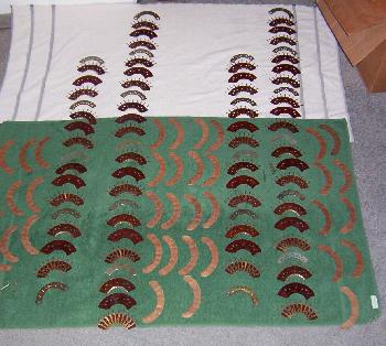
But the cleaning wasn't just needed for the contacts; the phenolic wafers needed a lot of work, too.  There was lots of dirt on the tops and edges, as one might expect, plus oil -- probably from routine maintenance of the banks -- had seeped in between the layers and was a sticky mess.  This photo shows two banks completely disassembled and drying after a good dose of Murphy's oil soap.


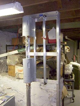
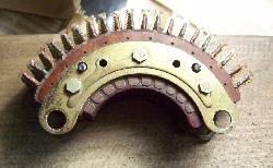
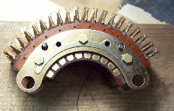
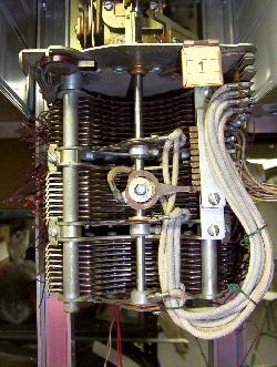
While there is still a lot of work left before they can be actually mounted on the switches, I couldn't resist and bolted two contact banks on the connectors and took a picture.  I also adjusted one set of wipers that I could tell even without banks were out of whack.  Slowly, it's beginning to look like a complete step switch.

Currently, the rewiring of the connector banks is taking place.  Seven levels of the T/R banks are done as of today.  The sleeve banks remain to be done.


21 January -- Nine levels of the line banks for the connectors are now wired. Rewiring was necessary due to a couple of factors, namely the extent of the dirt & tarnish on the contacts which needed a thorough cleaning, and my connectors are farther apart than the standard phone company spacing.  Also, with planning to implement 50 or so lines, it was easier to rewire from scratch than to splice into existing connections.

25 January -- The line banks for the connectors are done and reassembled.  Need to start on the sleeve banks.  Received confirmation late this week of the shipment of the line finder banks and the equipment jacks.
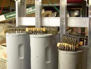
26 January -- The shelf/equipment jacks arrived today!  I need to start wiring those sleeve banks!!  Also, before I mount the equipment jacks I need to move up the lower row of switches.  On advice of a fellow ATCA club member far more knowledgeable than I about switches I am told that it really would be best to mount my switch rows closer together.

28 January -- Two levels of the connector sleeve banks are wired.
31 January -- Seven levels of the connector sleeve banks are wired.  In yesterday's post were the line finder banks!  Nearly all of the parts to complete the switch are now on hand.  About the only thing left to get are line & cutoff relays.  The line finder banks will need rewiring like the connector banks, so it will be a while before they'll be ready to be mounted on the switches.

Yesterday I picked up the hardware for mounting the shelf jacks on the switch frame.  That will be the next mechanical work to be done, probably when the sleeve banks are completed.
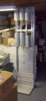
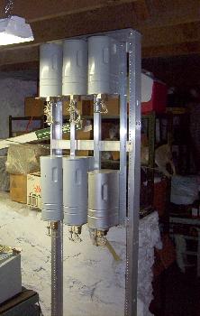
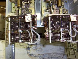
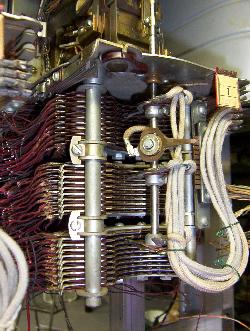
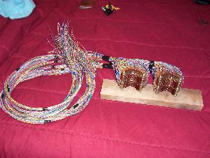
1 February - The connector contact banks are done!  Here's what they look like with their new cables that will eventually go to terminal blocks on the switch frame.
Here's some close-ups of the completed banks.  That's 200 pairs of wires!!  And I'll have to do it again with the line finder banks!

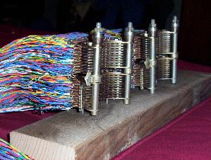
2 February -- cut apart the line finder banks that arrived in a string of three.  Like the connector and selector banks, these banks need some TLC and the only way to work on them is to separate them.  With the banks separated, I decided to put the best of the three on a line finder switch and see if I could make the switch "find" a connection.  That led to the first setback of sorts in the project.  When the line finder is searching for the station desiring service, it is looking for a resistance path (through the cutoff relay) to battery in order to stop the hunting.  It turns out that the surplus 48V relays, around which I designed a printed circuit board for line and cutoff relays, have a coil resistance that is too high for the line finder to "see" when hunting a line.  Looks like I am going to have to find the real McCoy and not back engineer my own.  I am also very glad that I waited to check this out before I spent big bucks on getting circuit boards made...
However, all is not lost!  I dug around and found some 2-watt resistors and built up about 800 ohms' worth of resistance and clipped it to a sleeve lead on the line finder bank.  I clipped ground to the level commutator that went with the sleeve lead, and grounded the 'start' lead of the finder.  Voila!  It found the "station"!!   Pictured here is the finder resting on terminal 85.  This project is beginning to be a LOT of fun!


Read More:
Current Progress   Feb 2004 - April 2004    May 2004 - Aug 2004   Sept 2004 - Dec 2004    Jan 2005 - Jan 2008

Back to home

Back to the Phones Page

Send me e-mail


Updated February 7, 2009