Doug's SxS Switch -- The Early Days   
Current Progress   Dec 2003 - Jan 2004    May 2004 - Aug 2004   Sept 2004 - Dec 2004   Jan 2005 - Jan 2008


February 2004 - April 2004


5 February -- a fair bit to report.  Started disassembling a line finder bank, and since these particular banks date from the late 1940s, they were soldered rather than crimped like the selector and connector banks, so they will take longer to take apart.  I have 5 levels of the lower line bank apart so far.

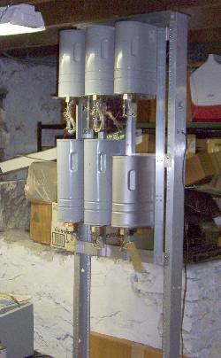
I cleaned up the solder tabs of the equipment jacks in preparation for mounting on the switch frame.  This evening I got into the mechanical work of the switch frame.  First, I raised the lower row of switches by about five inches or so.  
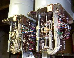
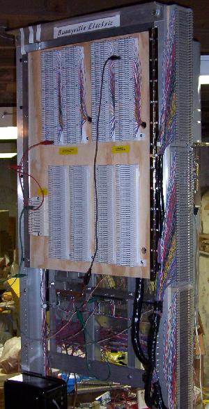
With that done I started building the equipment jack framework on the back.  I found some "plywood edging" at the hardware store that appears to be perfect for mounting equipment jacks.  Two equipment jacks (left and center) are now permanently mounted on the lower row.  It's really beginning to look like a switch now!  In the original full-size pic of this shot, I noticed the date code on the back of the old selector on the left - Feb 4 1942!! Happy 62nd Birthday Mr. Selector!

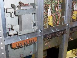
7 February -- A good day was spent at the switch frame.  After work yesterday the upper switch row's equipment jack rail and jacks were mounted.  Today the wiring of the jacks was begun.  At this juncture, only battery, ground and release battery lines have been attached, but it is enough to be able to work with and troubleshoot the switches.  Everything was nicely done on the jacks when I suddenly realized I had reversed the battery and release battery lines!  Some remedial work with the soldering gun switched the leads around the way they should be.  Wouldn't that have been interesting if left unnoticed and connected to the release battery alarm!
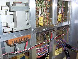
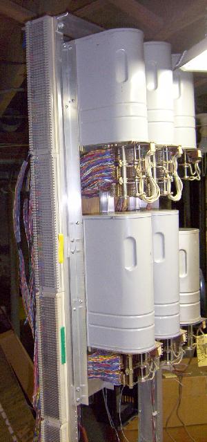
Other work done on the frame today included the mounting of a 211 "Spacesaver" set on the right side, and the rewired connector banks were attached to the connectors.  With the banks in place the wipers of the connectors were adjusted to contact properly and testing of the connectors could take place.

A lot of time was spent with the 30200 1942 selector (lower right, next to the phone).  With new info in hand from a kind phone call from a fellow switcher I attempted to test the selectors.  The newer 32077 digit absorbing selector worked as expected and appears to be wired to absorb digit "3" if dialed first.  The 30200 was a different story.  After a lot of puttering and dignosing it looks like the switch is not contacting the shelf jack correctly.  I can't see how it contacts since the rail that holds the jack blocks the view of the contacts, and that older selector has quite a framework on the back of it to hold a large capacitor.  More work will be needed with that.

8 February -- A major step (pun!) forward!  I first had at the old selector that wasn't operating correctly yesterday and burnished jack contacts on both the selector and the frame jack.  It still wasn't right so I loosened the bolts that hold the jack to the frame and gave it a good wiggle on the selector and suddenly everything was working the way it should.  I had an idea that it was a contact problem all along.

I then took a selector contact bank that still needs some TLC (read: it's grimy and generally filthy) and I attached tip, ring & sleeve leads to two contact sets on the bank and bolted it to the vintage 1942 selector.  I connected the T, R & S leads to the two connectors on the frame, attached the "frame phone" (the 211 spacesaver mounted yesterday) to the selector T/R input, went off hook and dialed a "2" (the level on which I attached the T/R/S leads).  It worked! It stepped up two levels, and cut in to the first selector.  Dialed two more digits and the connector responded accordingly.  Too cool!

I then "busied out" the first selector and dialed a "2" again.  The selector, as expected, stepped up and cut in to the second connector which then responded to the next two digits.  The switch works!

In the excitement of the moment, I pulled out my ancient laptop and recorded some wave files of the switch at work.  Here they are:

The first file (157 kb) is of a line finder coming alive and finding terminal 85, then resetting.  There are no actual stations attached to the finder yet.  I'm still pulling a contact bank apart for cleaning and rewiring.

The second file (283 kb) is the selector and first connector dialing "279" then resetting.

The third file (294 kb) has the first connector busied out so the selector cuts in an extra step to get to the second connector and the total dialing string is "205" so there's a bit more stepping going on with the second digit, then everything resets.

In contact bank progress, the lower line bank of a line finder bank has had its original wiring completely removed.  The middle line bank has seven levels cleared of the original wiring.

11 February -- The first line finder bank has been unwired completely as of a couple of days ago.  Next is to burnish and clean the contacts on all the wafers.

Tonight I got the connectors to ring through to a dialed station.  I had tried that when I got the selector going but it wouldn't work and then later realized that I had missed the "gen ground" connection.  Tonight I didn't forget that one and I was able to apply ringing current through to the called line.  I have no interrupter going yet, so it was definitely a clip lead connection!

I also built up a circuit to allow connections out of the switch into other systems, namely the telco line into the house.  Attaching to a ninth level terminal on the selector, I was then able to dial "9" and call out on the "real" phone line.  Things are still pretty rough and can be considered a breadboard or experimental mode.
12 February -- Got some PIC chips today and programmed up one to do dial tone, busy tone and ring machine interrupter.  Works great on the work bench, now to build up the perf board with the final circuit.  The circuit is based on a 16F84, and provides a steady dial tone, an interrupted busy tone, and cycles a relay that will provide the ringing cadence and trip power to the connectors, governed by the grounding of the Ring Machine Start lead from the connectors.
14 February -- The interrupter/tone board has been constructed.  It was not without incident having accidently connected the +5V line to the +12V line on the workbench when testing and blew a 16F84.  Fortunately, more than one was purchased...  The completed board was connected the various correct places on the switch and tried out.  For the most part, it works.  Dialing through to an attached station results in the selected station ringing and cutting through when the called station is answered.  Only problem was that the interrupter board became unstable when a called station was in the ringing mode.  I had broken Rule #1 in digital electronics: use decoupling caps everywhere!  (it worked great on the bench!)  Adding a few caps to the board in strategic places resulted in the board operating correctly.

It would also appear that the "ring machine start" input on the interrupter board will operate more reliably if triggered by a relay contact right on the board and not running a long lead up to the RM Start pin on the connector jacks.  One less "antenna" to pick up the transient spikes of the relays operating in the switches.  Ah, nothing like marrying old and new technology!

Busy Tone applied to the correct pin on the connectors worked some of the time, and appears to be unrelated to the decoupling cap problem noted with the ringing sequence.  Looks like more dirty contacts, probably in a relay in the connector.  That'll be "fun" to chase out...
15 February - installed the tone/interrupter board on the switch frame, down at the bottom by the 48V power supply.  Found that the second selector (the one in the middle of the bottom row) has some contact issues.  Seems like it doesn't take a lot of poking around with the relay contacts to render a problem of some kind in it.  Among the problems encountered today were no release on disconnect because the vertical off-normal contact that connects to the release magnet suddenly decided to not make correctly.  Busy tone comes and goes with this selector because whatever contact that allows the "G" relay to pull in doesn't always let it.  Also had a problem with the "K" relay pulling in correctly due to contacts on the "H" relay being ornery.  Running a slip of paper between the contacts to clean 'em up seemed to make things worse rather than better!  I'm open to suggestions on taming these ornery contacts.

In contact bank news, the lower line bank from the first finder set has had its contacts cleaned up.

Also had an unexpected success on eBay.  Stumbled across someone selling a solid state 20-cycle ringing supply whose auction was ending shortly with no bids.  Won the auction and am awaiting shipping details from the seller to close that deal.  I had been watching an old Lorain static ringing supply that's up on eBay but I would much prefer the newer, smaller supply, and it gets powered from the 48V supply, so there won't be an extra transformer spinning the electric meter.  For testing I have been using a key system supply, but of course those put out 30 Hz ringing power.  It will be nice to have the "real" 20 cycle supply!
16 February -- I tried cleaning the "E" relay's contacts in that second connector with a swab of contact cleaner.  It was partially successful; the connector now connects to the ring position reliably, but still does not connect to busy every time that it should.  Need to study the schematic and see just when & how the "E" relay's contacts should move and try adjusting them.

Dug around in a box of old telephone parts & etc. that a friend gave me a long time ago (thanks, Brian!) and found what looked like a heavy duty coil.  It's marked "Rep 202A" so I am assuming it's a repeating coil of some kind, and hopefully perfect for a dial tone transformer.  Did some checking with an ohmmeter and found the various windings and then clipped it onto the selector's dial tone input pin.  It worked!  The dial tone level, though, is a bit low but there's a 10K resistor in line with its output from the PIC controller so I may be able to throttle that back a bit to bring up the DT level.

21 February -- It was a busy week so I didn't get a lot done on the switch.  All three contact banks of one line finder bank have had their contacts cleaned up.  The sleeve bank is a bit of a problem, though, since the contacts are glued onto the phenolic wafers with a shellac or laquer-like substance, rather than having points on them that snap into the phenolic as all the other banks are.  Some of the sleeve bank's contacts popped off during unwiring and cleaning and were glued back with super glue.  I have a feeling that more contacts will come off in the rewiring procedure.

Today the dial tone transformer was mounted and wired in permanently to the selectors on the switch.  Also, the volume level of the dial tone was raised by strapping a lower value resistor in parallel with the existing one on the tone/interrupter board.  The switch now has dial tone and busy tone.

Also, some exploration was done with the start lead chain of the finders to verify the operation of same.  The way Western Electric handles line finder allocation is when one finder is busy, relay contacts are closed in the busy finder such that the start lead is then extended to the next available finder in the group.  This was found to work just fine with the two finders that I have.

After studying some connector schematics this week, it was found that the errant busy tone in the one connector is likely due to dirty contacts in either the "E" or "K" relays, so both had another application of contact cleaner on a cotton swab.  Busy tone was still working in that second selector just before I powered everything down today.  Hopefully that problem has been solved.
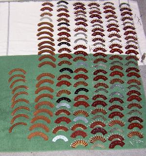
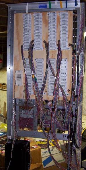
22 February -- Today I washed up all the wafers of the first cleaned up and unwired line finder bank.  It was quite a job as the photo would indicate.  With three contact banks in total there's over 150 separate parts to have to deal with!  They really needed the cleanup, however.

While those pieces dried I started to unwire the banks for the second line finder.  As of this wiring, the lowest line bank for that set has had its original wiring removed.

I am thinking that with only implementing well less than 100 lines in this switch, I will wire up only the sleeve bank and the upper line bank for the finders.   I will also wire them straight across rather than in a "slipped" configuration that would be more "correct" for a set of finders.  Wiring slipped banks in a small switch with only two finders would not result in much of an advantage in terms of wait time for dial tone.  At a future time I may be interested in working with the lower line banks but for now I won't be wiring them.

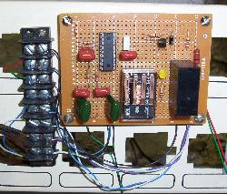
28 February -- Spent the week working with the eBay ring generator board which arrived.  There was no paperwork with it (nor expected) and after an evening of Internet searching some of the basics of the board had been discovered.  Namely, the board was not strictly a 48 volt input-ring power output supply, despite its eBay write-up.  The board requires 20 VAC input, generates its own 48 VDC, converts that to ring power output, and provides superimposed ring and trip power out.  Sort of.

Today the ring supply board was mounted on the switch frame in the lower area with the other power supplies and interrupter board.  While the board does supply 20 Hz ring power, the trip supply appears to be a bit weak for a step switch.  Answering a ringing station during the ring phase results in getting rung in the ear.  During that situation you can hear the "F" relay trying to pull up in the connector, but it can't quite make it.  It's not a big disappointment since it wasn't expected that this board would be supplying superimposed ring voltage.

In contact bank work, the second line finder bank is still having its original wiring removed.

29 February -- Cleaned and burnished the contacts of all levels of the second line finder bank.  That was followed by a full disassembled wash of all the wafers of all the banks in preparation for rewiring (see photo with 22 Feb above, it looked just like that again!).  Once all the bank parts had dried, the banks were reassembled and wiring was started on the middle line banks.  One level is done!
2 March -- Rewiring of the middle line bank continues.  Four levels are now done.
7 March -- Nine levels of the middle line bank are now complete.  Progress is going to be a slow at the moment since the work to be done yet is contact bank wiring, currently on the line finders, and once those are completed, the selector banks.  Meanwhile, not much else can be done with the switch since I am lacking line and cutoff relays for the lines to be implemented.  I have a "want ad" coming soon in the March ATCA newsletter looking for L/CO stuff, so we'll hope for the best!
9 March -- The middle line banks of the line finder contact banks are done!  Now to start on those sleeve banks with the shellaced contacts...
11 March -- Three levels of the sleeve banks with the shellaced-in-place contacts are wired up.  So far things are going better than expected with these differently-mounted contacts.

In L/CO relay news, it is looking like I have a good lead (no pun intended) on a set of line & cutoff relays for my switch -- the last missing parts needed!
13 March -- Seven levels of the sleeve banks are now complete.  Ran into a problem on level 4 when two contacts snapped off the phenolic, as I had feared many would do.  A bit of super glue and they were back in place and the wiring could continue.  So far careful handling of the levels seems to be paying off.  Let's see how the last three levels go!
14 March -- Eight levels of the sleeve banks are done.  Getting there!

Spent a little time at the switch frame today getting ready to mount a panel on the back that will hold all the terminal blocks, and will swing out to all access to the backs of the switches.  Whilst puttering about at the switch I discovered that I had the ringing power generator hooked up backwards to the connectors, and was thus the reason that the connectors wouldn't "trip" during the ring phase.  The wires were reversed and now you can pick up a ringing phone and the connectors will trip and connect the call.
15 March -- The line finder sleeve banks are done!  The completed banks have been reassembled and are nearly ready to go.  The vertical commutator contact banks still need to be wired, but that won't be a particularly tough job compared to doing the banks.
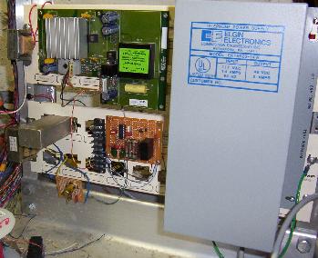
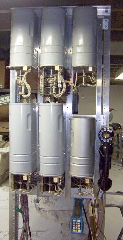
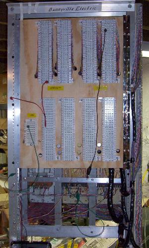
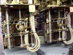
17 March -- A bout of snowy weather has work closed today, so what better time than to play step switch right now!  The vertical commutators for the finder banks were wired up and attached to the banks, and then whole mess was attached to the finders.  They went on fairly easily, though it did help to take the switches off the frame first, the banks set on the tops of the cans of the switches below and then the switches remounted and the banks bolted on.
Testing of the finders could now take place.  There appears to be some dirty contact issues in the switches, not unexpectedly after what has happened so far with the other switches.  The functioning of the finders could still be tested and through the use of clip leads and some resistors simulated line finding could be done.  There are no line & cutoff relays here yet to actually have the finders search for a "real" line.

The finders were wired to the selectors.  The first finder was wired to the 1942 30200 selector, and the second finder was wired to the newer digit-absorbing selector.  At the moment only the older selector has a contact bank attached so it is the only one currently that can have a complete call dialed through it.  The next task is to strip, clean up and rewire the contact banks for the selectors.

19 March -- One selector bank has been stripped of its original wiring.  The other selector bank is on the older selector and has some wires tacked into it for all the testing of the switch that has been going on.  I almost hate to pull that one off for stripping & rewiring since that will mean no selector work until the banks are done.

Spent a few moments this week looking at the terminal block situation on the switch.  I had originally thought I would mount punch-down blocks on a swing-out panel on the back of the switch, however it appears that the panel will not be big enough to hold all the blocks needed to tie all the line and sleeve connections together, even for a switch as small as this.  What I have decided to do is to mount the line terminal blocks down one side of the rack frame, and put all the sleeve and selector connections on the hinged panel.  The plywood panel has been cut and drilled for mounting on the hinges, only the layout of the terminal blocks is still to be decided.
27 March -- A week of no progress followed by a day of a lot of progress.  The line terminal banks were mounted on the left side of the equipment racks.  The routing of the wiring from the finders and connectors then ensued.  It's quite a rats' nest of wires!  Also, with the blocks down that side of the switch frame, the switch had to be moved out from its location to make it easier to work with the terminals.  That was not fun as the switch is quite weighty now, but it can be slowly "scootched" from side to side and gotten eventually to the desired postion.

A routing plan for the wiring was decided on and begun.  With the wiring more or less routed from their respective switches to the terminal blocks, terminating was started.  The first 25 lines are now terminated on the terminal blocks.  Pix tomorrow, hopefully.
28 March -- The wiring continues.  All 100 line pairs have been terminated on the side blocks pictured on the left below.  The hinged back panel which will hold the blocks for the sleeve leads and selector connections was drilled and mounted on the switch frame and the cable bundles for the sleeve leads routed through the holes in the panel.  I ran out of time before I could start dressing the cables in the back of the panel.

Line terminations
Sleeve termination panel

4 April -- The sleeve connections for the line finders and the connectors have been terminated on the rear panel of punch-down blocks.  It all worked out nicely, though I did make one error in the wiring, I reversed two cable bundles for the finders so the numbering of the terminals isn't neatly in sequence.  I labeled all the terminals so I can see where things are.

The photos below show the back of the switch as it now exists.  There are clip leads on some of the terminals for testing and verifying the connections.  The lower set of punchdown blocks on the sleeve panel will terminate the connections from the selectors.  I still need to get those selector banks rewired, as well as get the line & cutoff relays installed.  The relay units haven't shipped yet, but I am probably not quite ready for them.

Sleeve termination panel
Side view showing sleeve and line terminals

14 April -- A vexing problem was worked out today.  Over the last week or so the addition of a small box of 10 lines' worth of line & cutoff relays to the switch brought to light a problem with one of the line finders.  The finder in question would not stop on the terminal seeking service when the cutoff relay was on the sleeve, but a resistor of the same resistance as the relay on the terminal would have the finder stopping without any problems.  A study of the schematics ensued, along with seeking the advice of an experienced step technician.  After an exchange of emails pondering possible causes of the problems, it was suggested to me that the alignment of the sleeve wipers could be to blame.  I was out of town over the Easter weekend so I didn't get a chance to check out that idea until today.  That was it!  Both finders are now working perfectly.

With ten working lines connected on the switch, a few stations were hooked up around the house.  There is, of course, still a ways to go with the project.  The selector banks still need wiring and as of this writing only one selector has a bank with a few connections on it.  The bulk of the line and cutoff relays have not yet shipped so 10 lines are all the switch can provide at the moment.  A proper fuse panel needs to be wired up, and a proper release alarm needs to be built.

However, it is looking more like a step switch than at any time up until now!!
15 April -- Pulled out my spare 'OK' condition selector bank and swapped that onto the 1942 selector on the switch.  I can now disassemble and re-wire the 'good' bank that had been on that selector.  I have two good banks that will be wired together for the selectors and when they are in place and wired the switch will be nearly complete, at least in the number of working talk paths.  So far only one path has been working because I have had only one selector in operation.

16 April -- The selector bank pulled off yesterday had its original wiring removed, and one phenolic wafer replaced, thanks to having a "parts" bank on hand.  Burnishing of the level contacts can now take place, followed by a good wash, just as was done with the banks for the connectors and finders.

17 April -- The selector banks had their contacts cleaned & burnished, then all the wafers of the banks were washed up and dried.  Everything is ready for rewiring.  However, before that can happen I need to determine the cable length needed between the selectors since these sit atop each other instead of next to one another.


Read More:
Current Progress   Dec 2003 - Jan 2004    May 2004 - Aug 2004   Oct 2004 - Dec 2004    Jan 2005 - Jan 2008

Back to home

Back to the Phones Page

Send me e-mail


Updated March 11, 2017