Doug's SxS Switch -- The Early Days   
Current Progress   Dec 2003 - Jan 2004    Feb 2004 - April 2004   May 2004 - Aug 2004   Jan 2005 - Jan 2008


September 2004 - December 2004


3 September -- Five levels of the selector sleeve banks are now wired.  Received word this week that the Touch Tone to Pulse converters are on their way to me in the post -- that will be great to get TT capability going in the switch!

I am also as of this week in receipt of two more line finders, courtesy of a reader of this site -- thanks, Neil!  Both finders are Canadian manufactured Northern Electric switches, which should work OK with the switch here.  The one switch is nearly new and I am thinking that I will swap out that troublesome second WE finder on the switch with this very clean NE model.  The other NE finder is a neat older version of that switch, though I cannot find a specific date on it.  I have been thinking about building a small, portable "demo" switch and this older finder would be a nice match, vintage-wise, with that older 30200 selector I have on the big switch.  Need to come up with another selector, though, and maybe something digit-absorbing to go with the 32077 DA selector already on the switch so I can implement 4-digit dialing.

But I am getting ahead of myself; I need to finish the "big switch" first!

9 September -- Seven levels of the selector sleeve banks are wired.

Yesterday the box with the Touch Tone converters arrived.  Had a moment this evening to hook one up to the line finder of the one working path I have on the switch.  It works!  Hookup is very simple: it drops into the trunk between the line finder and the first selector along with battery and ground and away we go.

I need to add another bracket on the back of the switch on which to mount the TT converters.  These were made to hang behind "real" step switch shelves that have a convenient angle bracket on which to bolt the converters.  Since my "shelves" were built from scratch by me that rail doesn't exist.  For the moment I have the converter hanging on the top angle stock that holds the side rails together.

14 September -- Installed a rail on which to mount the Touch Tone converters and mounted the already-wired converter on it and then wired in a second converter to the second line finder on the switch.  The photo at the right shows the mounted & wired converters.  Now both switch paths have Touch Tone capability, even though the second path isn't completely working yet.  There's still only seven levels of the selector sleeve banks done.

Got an email from a fellow switcher over the weekend saying he has the shaft spring for the older NE line finder I got a few weeks ago that is missing same.  That should complete that finder, which at the moment is earmarked for the Portable Demo Switch Project, to be started after I get some more stuff done on this big switch.

19 September -- It has taken nearly a month, but the sleeve contact banks for the selectors are now wired completely!  The sleeve banks were reassembled with their line bank counterparts and the selector contact banks are ready for installation.  Progress indeed.
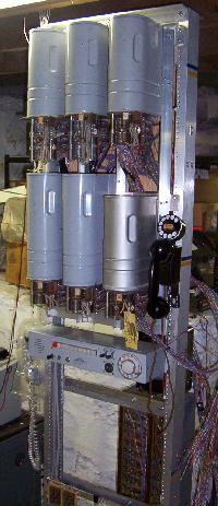
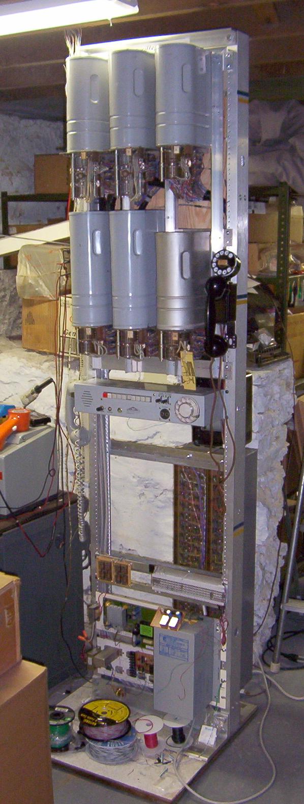
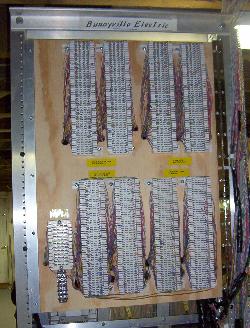
25 September -- Lots of progress on the switch!  The completed selector contact banks were bolted onto the switches.  Temporary connections to the connectors was made to the new bank wiring and tested -- it works!  The switch can now support two simultaneous connections.   The cable bundles to the banks still need to be dressed and terminated properly, so in the photo at left you can see the wires hanging out the right side of the switch.

An interesting rack-mounted telephone, made by Allentel and pictured at the right, was discovered and purchased and mounted on the switch frame.  It can be seen below the switches in the photo.  The phone is basically a 1A2 multi-line telephone, with a speakerphone component and the capability of plugging in a standard telephone headset, or using the attached handset.  I don't know if these were ever used in switch rooms, but it looks like it *should* be there!

10 October -- The cables for the selector banks have been dressed and terminated on the back swing-out door's punch blocks.  No more clip leads, bare connections or other temporary wiring!  The switch now properly supports two simultaneous connections.

Also had at that second line finder again.  It has been refusing to find a station on the first level, stopping always at the first terminal no matter which station on that level was off hook.  It was working OK on the other levels, at least in the rotary stepping arena.  It was not finding stations off hook on some terminals on some levels, though was working fine for other stations on the same level.

The first level problem turned out to be the lower set of line contacts on the shaft. They were slightly out of alignment and the first level's terminals on that lower (and usused in my switch) line bank were a bit beat up at the leading edge and was missing some of the insulating wafer between the contacts.  As a result the wipers would bash into the sides of the first set of contacts which would hold up the shaft.  The other levels worked OK because the insulating wafer was complete and would help guide the contacts onto the level correctly.  Those wipers were adjusted slightly and the finder now hunts on the first level.

The other problem with that finder not finding every station every time on a level was related to a slight adjustment problem with the sleeve bank wipers.  They were slightly "forward" in their position and thus were not on the sleeve contact long enough for the switch to realize it, essentially the same problem I had with the first line finder back in April.

While that second finder is now working correctly, I still think I will swap it out for the very clean NE finder I got this summer.  I still have to test that NE switch and make sure it works OK.  Also, a shaft spring has been located and received for the second (older) NE finder (Thanks, Chuck!).  That older NE finder appears to be complete except for the shaft spring so now that switch can be tested, too.

16 October -- Earlier in the week the connectors were wired to two different levels on the switch.  The main reason for this was to set a different selection order of the connectors on a different level.  The selection was reversed on the "5" level so when that level is dialed the second connector will be selected first.

Today a drop cable was wired from the house MDF to the Allentel "frame phone" on the switch frame.  The phone was crossed into various lines on the 1A2 house key system.  More step switch lines will be wired to the frame phone as they are added to the 1A2 system.

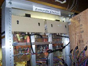
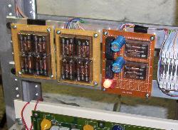
17 October -- The external trunk circuit board was installed and wired on the switch frame today.  While not a true "repeating trunk" it does provide access to an external telephone loop.  Two circuits were built on the board some months ago (see 25 July) and one was wired to the "real" phone line into the house and the circuit was attached to the "9" level on the selectors.  Dialing 9 from any step station draws dial tone from the CO.

The other trunk circuit on the board was wired to the 1A2 dial intercom in the house and the circuit was attached to the "8" level on the selectors.  Dialing 8 cuts the calling step station over to the dial intercom and you can then dial into that system.

The picture at left shows the two group relay boards on the left and center and the trunk board on the right.  There is a large dual-color LED on the board (near the bottom of it) that indicates which circuit is active, in this case it is glowing red indicating a station has dialed through to the 1A2 intercom.

Another step line wired into the 1A2 system was connected to the Allentel frame phone.

Now I need to get at those last two plates of line & cutoff relays to get those last 40 stations "lit" on the switch.

24 October -- Lost one of the Touch Tone converters on the switch this week.  It was the one on the first finder/selector path and was working fine earlier in the week but wasn't working Friday evening.  I am told by another switcher that these old TelTone converters do that, they just up & quit for no apparent reason.  Fortunately I bought a bunch of them and was able to swap out the bad one for another working one.

I started wiring another plate of line & cutoff relays today.  One half, or ten stations' worth, is completed.

Also put the shaft spring on the older NE finder to complete that switch.  Just toying a bit with the switch on the bench I find that it needs some mechanical adjustment here & there, but it doesn't appear to be as badly out of whack as the one WE finder currently on the switch.  I need to take the 8-party connector I have been experimenting with off my switch test stand so I can get this NE finder on its way to proper operation.

October 31 -- The cable wiring to the third plate of line & cutoff relays was completed this week and installed on the switch yesterday.  The wiring into the switch from the plate was done and now there are another 20 ports "live."  There is, however, a problem with the cutoff relay for station X79.  The CO relay is out of adjustment will not pull in without outside help.  I attempted to adjust the relay and it worked without help for a little while but obviously the right adjustments haven't been made as it will not pull in again unassisted.

The photo at the left shows the three plates of L/CO installed.  The cover on the newly installed one needs to be repainted so it isn't as nice looking as the first two.  The black box just above the plates is the subset for the frame-mounted 211 "Spacesaver" set.  The photo at right shows the rear sleeve termination panel as it exists at the moment.  The punch blocks on the top are where the sleeves for the connectors (left two) and line finders (right two) terminate.  The lower blocks are the sleeve and line terminations for the selectors, sleeves on the left two blocks, and lines on the right.

14 November -- It's been an interesting couple of weeks with the step switch.  A recurring problem in the second connector cropped up again not long after the last update, namely the busy tone does not cut through correctly.  This problem was noted earlier with this connector (See 15 February).  In addition to not cutting busy tone when it should, it was also now not cutting battery through when a called station would go off hook.  Some careful poking around lead to the conclusion that there is probably some contact issues with the other relays, notably the (F) relay.  Asking for help from some other switchers yielded various advice ranging from "observe and adjust [the contacts] carefully" to "don't do anything without full docs on the switch and its relays, as well as having all the right tools & metering equipment."  What to do...  It was decided that before trying either approach to get the rest of the docs for this connector from Lucent.  Already on hand are the Circuit Description (CD) and Equipment Diagram (ED), so last in the puzzle is the Schematic Drawing (SD).  As of this writing it is on order but not yet received.  Meanwhile the switch has started working correctly again after doing some manual exercising of armatures of the (J) and (K) relays in the connector.  Definitely a contact problem of some kind...

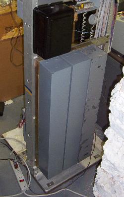
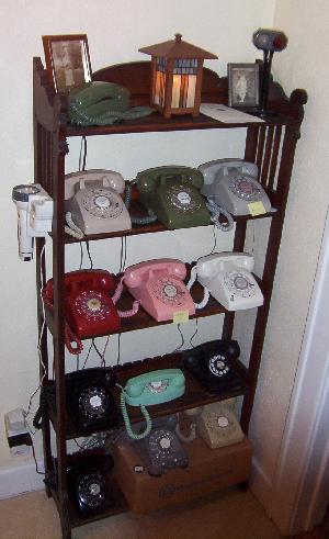
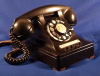
In somewhat related switch news, I have started playing with a pair of old 1B KTUs from a 1A key telephone system.  They are intended for use with phones like my 440, (see left and on my phones page).  The plan is to attach two step switch lines to the little box of 1Bs and to that attach the 440 and a 544 telephone I have.  It hasn't been a good time for relays in my shop... one of the 1B KTUs was always pulling in to the hold position without even a telephone attached to it.  After an evening and afternoon of puttering with it, it would appear that there was a solder blob or other metallic debris inside the (L) relay of the problem 1B KTU because eventually something went "klink" inside the relay and everything appears to be working OK again.

I need to start thinking seriously about modifying the program in the PIC chip tone generator/interrupter to provide two more tones: a steady tone to mix into the ringing supply and a reorder or "fast busy" tone for the all circuits busy condition on the selector levels.

26 November -- Not much progress on the switch this week, but a number of stations were wired to it.  I have a small collection of mostly WE 500 sets in various colors and they are displayed together in one place in my home.  All of the phones in the display, pictured at the right, are now connected to the step switch.  The only one in the photo not connected is the multi line Stromberg-Carlson set on the middle of the bottom shelf.  The blue/green Princess phone is an early 701 model without its own internal bell so it shares a step line with the green round button Trimline set on the top shelf.  The white set on the right on the middle shelf is a two-line ITT set and is wired to its own line, plus the line of the beige NT set two shelves below it on line #2.

18 December -- A couple of busy weeks has seen no new work on the step switch.  Between holiday preparations and my back going out on me for almost a week there hasn't been much time to deal with the necessaries, let alone hobby stuff.  I have, though, been looking at the code in the PIC chip for adding all circuits busy and a ring tone output to the chip so those things can be added to the step switch.

However, in nearing the first anniversary of starting to construct the switch, I think things are rather well along, with more yet to come.

30 December -- Did some auxiliary work related to the step switch.  Today I added another six-line 1A2 KSU (a 501 for those in the know) so I can accomodate more step switch lines to the various 1A2 stations around the house.  Two step lines were connected to the addtional KSU and the appropriate stations connected to it.

31 December -- Time for some glitz again... made some recordings of the switch in operation.  The only other recordings I have had on this site so far are from when the switch wasn't completely operational.  The sound bites here are also done as MP3 files to conserve my quickly disappearing web space.

Dialing the Frame Phone - In this file the test set goes off hook and dials 555, the 211 Spacesaver on the switch frame.  On the 5th level of the selectors I have the connectors wired farther over on the level so the selectors have to hunt farther.  Upon dialing the station, the frame phone begins to ring, is picked up after a couple of rings and everything is placed back on-hook.

Dialing a Busy Station - In the next two files I am recording what comes out of the speaker phone of the Allentel rack-mounted telephone so one can hear the progress tones.  There is some static-like noise in the speaker phone, probably from the key system power supply I am using to operate the speaker phone.  The key system supply has a 30 Hz ring supply and noise from that is getting into the speaker phone.  However, you can still hear what is going on.  The phone goes off hook and gets dial tone and dials an engaged station so the connector returns the busy signal.

Ringing a Station - Again, a recording made from the Allentel speaker phone.  The phone goes off hook and gets dial tone and calls an idle station and lets it ring a few times and then goes back on-hook.  At the moment I have no superimposed ringback tone on the switch.  The buzzing noise that serves as the ringback tone is the little bit of ring current that the connector couples into the talk path.


Read More:
Current Progress   Dec 2003 - Jan 2004    Feb 2004 - April 2004   May 2004 - Aug 2004   Jan 2005 - Jan 2008

Back to home

Back to the Phones Page

Send me e-mail


Updated March 11, 2017