 | Current Step Switch ProgressClick to go to the most recent entry |
| Doug's SxS Switch |
| Current Step Switch ProgressClick to go to the most recent entry |
 10 January 2009 -- Well, here it is nearly a year later with no updates or progress to report on the big switch. However, a new project has finally started:
construction of a small, portable step switch! The plan is to have it fully operational in time for a debut at the June 2009 Lancaster, PA Telephone Exhibit hosted
by Telephone Collectors International. There the switch will be on display and operational. Information about the show itself is on this page:
http://www.telephonecollectors.org/events/events.htm
10 January 2009 -- Well, here it is nearly a year later with no updates or progress to report on the big switch. However, a new project has finally started:
construction of a small, portable step switch! The plan is to have it fully operational in time for a debut at the June 2009 Lancaster, PA Telephone Exhibit hosted
by Telephone Collectors International. There the switch will be on display and operational. Information about the show itself is on this page:
http://www.telephonecollectors.org/events/events.htm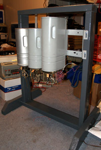 14 January -- Mounted the shelf section on the switch frame today and hung a couple of switches on it for grins and took a photo. There's a long way to go yet,
and nothing is yet operational, but we can get an idea of what the switch will look like. The area under the switches will hold the control circuitry like the line and cutoff relays, line finder
circuits and possibly a trunk plate for connecting to other systems.
14 January -- Mounted the shelf section on the switch frame today and hung a couple of switches on it for grins and took a photo. There's a long way to go yet,
and nothing is yet operational, but we can get an idea of what the switch will look like. The area under the switches will hold the control circuitry like the line and cutoff relays, line finder
circuits and possibly a trunk plate for connecting to other systems.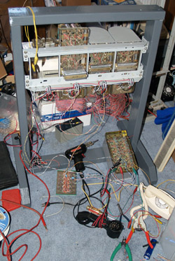 1 February -- Been busy this weekend working on the portable switch. Yesterday I wired up a line finder board and got it tacked into the switch for testing. I found that I have another setback in the
project; discovered that the line finder circuit will not "play nice" with a second finder board. Stations going off hook after one station has been seized on the board will also be
seized, dropping the next station(s) into the existing conversation. Not good. I am looking at how full control can be passed from one board to the next but unfortunately it's not as simple
as passing the start lead on to the next board; I am already doing that and that's when I discovered the problem. I am currently studying my schematic and seeing how I can manage to
have two of these all-relay LFs coexist with each other so that I can have a two talking path switch. I don't have the luxury of the original SxS engineers having things like many multiple pole relays at their disposal, I have only 4PDT relays!
1 February -- Been busy this weekend working on the portable switch. Yesterday I wired up a line finder board and got it tacked into the switch for testing. I found that I have another setback in the
project; discovered that the line finder circuit will not "play nice" with a second finder board. Stations going off hook after one station has been seized on the board will also be
seized, dropping the next station(s) into the existing conversation. Not good. I am looking at how full control can be passed from one board to the next but unfortunately it's not as simple
as passing the start lead on to the next board; I am already doing that and that's when I discovered the problem. I am currently studying my schematic and seeing how I can manage to
have two of these all-relay LFs coexist with each other so that I can have a two talking path switch. I don't have the luxury of the original SxS engineers having things like many multiple pole relays at their disposal, I have only 4PDT relays!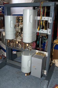 | 16 February -- Spent some time doing mechanical work on the switch frame. The mounting rails were drilled and installed for the L/CO plate and the
trunk plate. The switch as it appears at the moment is pictured at left. Nothing is yet wired up, and the shelf jack for the trunk plate still needs to be installed. However, it
is definitely progress. The L/CO plate also needs a mounting bolt drilled and installed to hold the plate on the frame. That will not be removed when the switch is moved and will be
wired in permanently, so the bolt will be needed to keep it from sliding off in transit. The next mechanical puzzle will be to figure out how the line finder boards will be mounted in the area to the left of the trunk and L/CO plates. I am leaning toward having the two LF boards stacked and mounted as one unit. I haven't had a chance to sit down and really look at the one LF board and think about the best way for mounting it securely. The interrupter and ringing board will be mounted to the left of the trunk and L/CO. There will also be a board with the old dial/busy tone recording that will be interwired with the interrupter. What looked like a lot of space in the lower part of the switch is quickly disappearing! |
 | 22 February -- Been puttering with the portable switch over the last few days and now have the shelf jack mounted and installed for the trunk plate (picture at
left). With that completed the L/CO plate could be permanently mounted so that was bolted into place and a punch down block was installed and the fly leads from the L/CO that I installed last week were
terminated on the terminal block. The connector banks and line finder boards will all terminate here to help with the wire management of the switch. Another punch down block is planned for the other side of
the back of the switch to manage the selector connections. With the trunk plate now on a connector, I did a little testing of the unit since I have not had power to it before. I have documentation for it so was able to put the right inputs in the right places and have it work. There are two trunk circuits on the plate and both appear to be working fine. In other work, today I got the ringing and interrupter board closer to completion by mounting a 12V regulator on that board. I have a nice nominal 12V power supply, but the Black Magic ringing supply on the board wants to see between 11 and 14 volts, but this supply puts out over 16 no load. So I put in the regulator to keep from frying the Black Magic chip. |
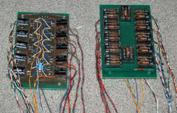 | 1 March -- Spent the weekend finishing up the first line finder board and building the second one. They are pictured at left. Now I need to mount them on the
switch frame. I think I have worked out how I will do it and will utilize another punch down block in the back of the frame to help manage the wiring. Step switches are rather simple
affairs, but the intra-switch wiring can be a real bear! Lots and lots of leads to keep track of, even in a small 10-station switch like this is going to be. I need to make a trip to the hardware store for a few sundries to help with the mounting of the boards on the frame, but the project is moving along. Someone on one of the phone club email lists noted this weekend that it is 15 weeks until the Lancaster, PA show... so I gotta keep at it! |
 |
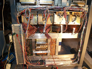
22 March -- The project is moving along well. Spent the week working with the contact bank for the NE line finder and got a level wired up to a DB37 connector, and made up a cable with a matching connector to wire
into the switch frame. I made some preliminary tests Friday evening and the finder wasn't working quite to spec, so it was time to dig out the docs and study up on the line finder's operation. As usual, it
was a dirty contact in the "B" relay, combined with wipers that weren't quite in exact alignment. By Saturday afternoon the finder was connected to the L/CO and each line would be properly
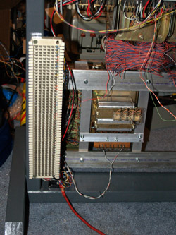
found when going off hook. Then it was on to a selector bank. A bank was wired with an outlet on each level so that the configuration of the switch can be easily changed for wharever application or demo it is involved in. Again, DB37s were wired to the bank and to a cable and connected to the switch frame and tested. The photo at left shows a close-up of the finder (extreme right) and first selector from behind, showing the DB37s. When the switch is transported, the bank connectors will be pulled and the switches removed from the frame and transported separately to reduce the overall weight. Next to be done are to put connectors on the contact banks for the second selector and the connector/final selector. |
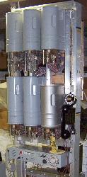
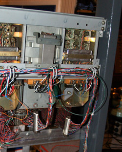
 View of the back. | 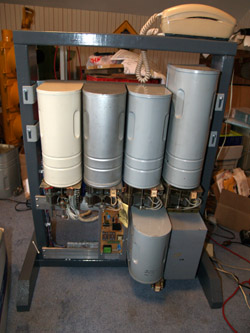 |
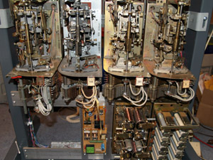 Close up of a call up on the switch. |
| View from the front. Equipment compliment across the top (L-R):NE 33014 LF, WE 30200 1st Sel (m'fd 1942!), WE 30200 2nd Sel, WE 31737 Conn. Bottom row (L-R): PIC interrupter board & ringing supply, WE 30779 trunk plate, AE L/CO plate. |
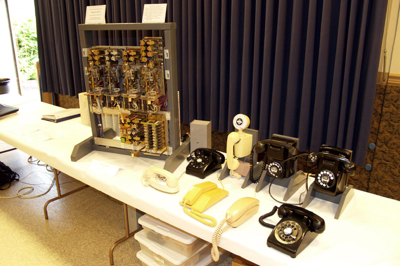 |
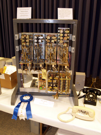
14 June -- The Lancaster phone show was last weekend and was a great success. There were over 70 tables of folks selling and exhibiting telephones and telephone-related
items. The "Switchers' Corner" was a big hit. There were three switch displays: mine, another small portable step switch with integrated C*NET Asterisk VoIP gear that served as the C*NET
gateway to the show, and a revertive signalling display with a "miniature" toll switchboard controlling a panel switch selector. Many show guests stopped to look, ask questions,
pick up a phone and dial, and there were a number of C*NET users from literally around the world that called in to the show through the step switches on display. Pictured at left is my portable switch on display with the phones that I had hooked up to it. I also brought some wall phones for which I built special stands so the phones could be displayed on a table. The surprise of the show, for me at least, was the ribbon I won for the "Most Educational" display. (photo below) It certainly made the last few months of work seem all the more worthwhile. I still can't believe that I won a ribbon for the first display I have done. There are more photos of the show posted on the TCI web site: http://www.telephonecollectors.org/events/lancaster09/lan09.htm. |